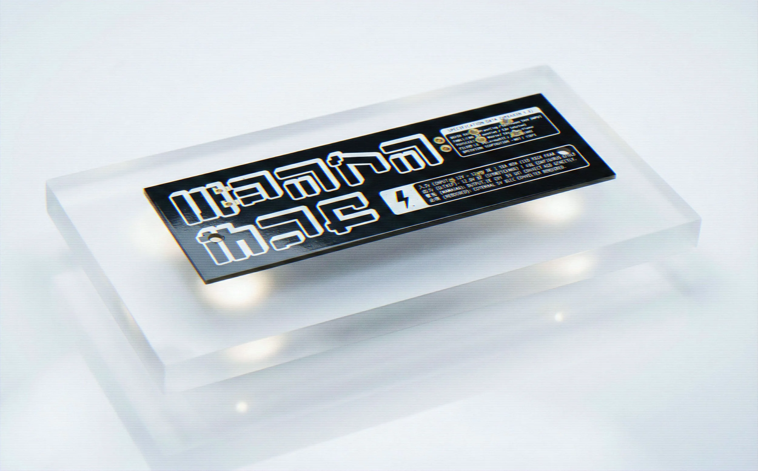
BUTT
*
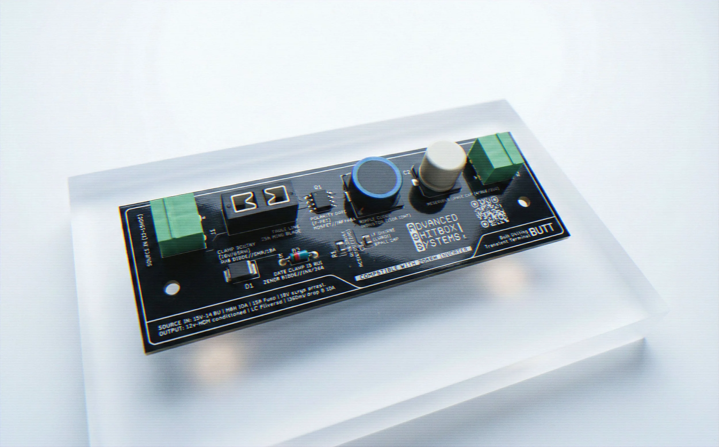
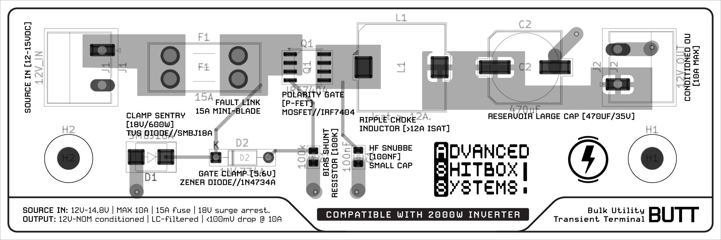
BUTT *
Bulk Utility Transient Terminal
While developing the DUMP, I discovered something obvious in hindsight: a vehicle’s 12V system is not a power source. It is an ecosystem. Alternator ripple, inductive spikes, load dumps, accidental reverse polarity, and general electrical hostility.
Microcontrollers, unfortunately, are polite.
The BUTT was created as a protective intermediary, a discrete power-conditioning board that receives unfiltered automotive 12–15V input and outputs something civilized enough to feed into a buck converter, and only then into sensitive logic systems.
It is not glamorous. It is necessary.
And once I started, it became its own project.
HOW IT WORKS:
The BUTT is essentially a layered defensive structure.
Input first passes through a 15A fuse. If something goes catastrophically wrong, it sacrifices itself. Intentionally.
A P-channel MOSFET polarity gate prevents reverse connection. No sparks. No drama.
An 18V TVS diode (SMBJ18A) acts as a surge sentry, clamping load-dump events before they reach downstream electronics.
An LC stage ripple choke plus reservoir capacitor (470µF/35V) reduces alternator noise and transient ripple.
A zener gate clamp stabilizes the MOSFET’s behavior.
The result is a conditioned 12V rail with minimal drop under load (<100mV @ 10A), ready to feed a buck converter without flinching.
The logic is simple: absorb violence upstream so downstream systems can pretend the world is stable.
PCB Design & Graphic System
Once the circuit was stable, the board had to explain itself.
The silkscreen is structured like a specification plate rather than a decorative layer. BUTT: Bulk Utility Transient Terminal, appears once, clearly, and then the board transitions into function.
SOURCE INTAKE leads into POLARITY SENTRY. DC RIPPLE ATTENUATION ZONE flows into SIGNAL CONDITIONING. SURGE PROTECTION and FAULT-LNK are not labels; they are statements of responsibility.
Every major stage publishes its parameters directly on the substrate. The transient clamp threshold is stated. The 18V working ceiling is stated. The 600W peak pulse capacity is stated. The LC filter declares its ~2.3kHz cutoff. Copper weight, temperature range, interrupt capacity all exposed without interpretation.
The MOSFET stage identifies itself as POLARITY GUARD and even reveals its gate-source clamp values. The fuse specifies what it can interrupt. The TVS diode states exactly how much violence it will tolerate.
The result is not graphic design in the conventional sense. It is embedded documentation. The board reads like something that expects inspection — and is prepared for it.
PCB Design &
Graphic System
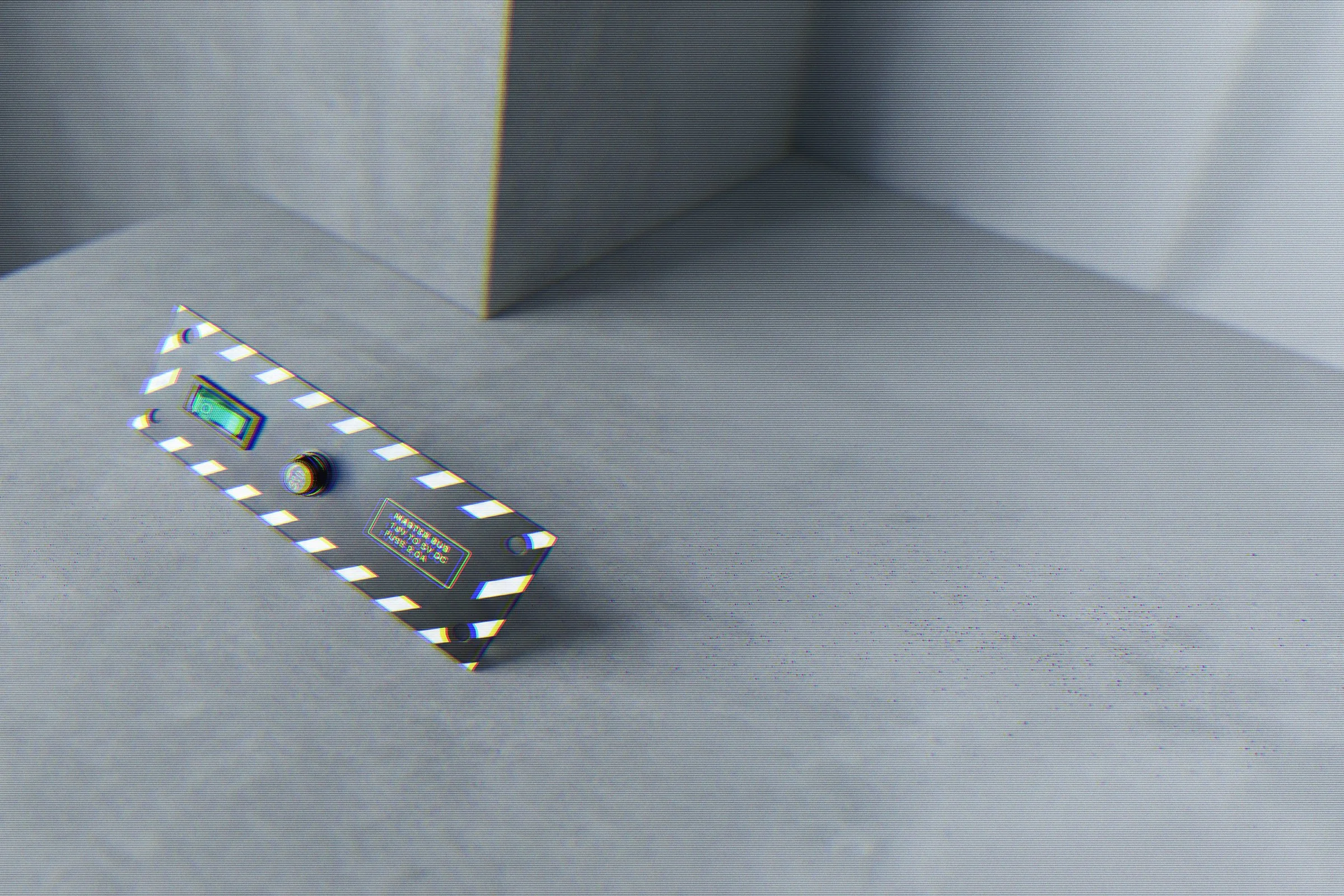
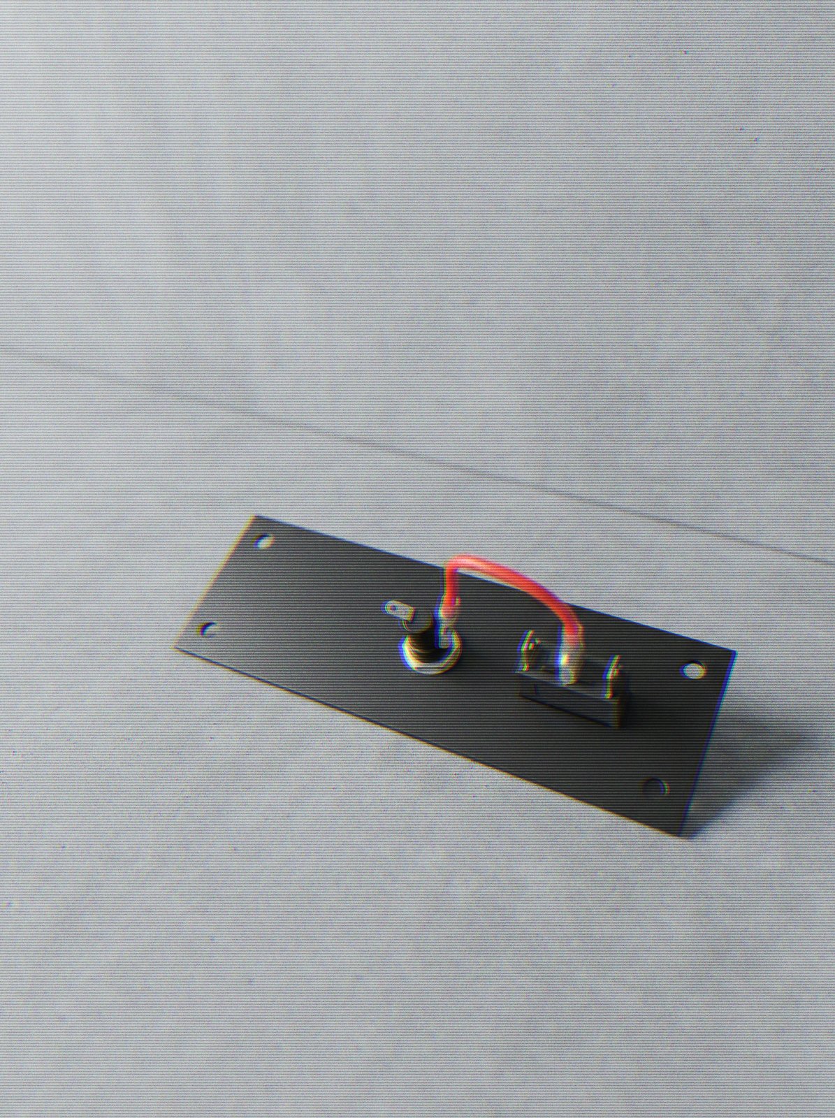
The BUTT includes a fused master switch mounted on a dedicated faceplate.
Aviation-style. Deliberately tactile.
Power is not assumed. It is enabled.
The switch visually communicates that something consequential is happening when engaged — which, in an automotive environment, is generally accurate.